::April 2018::
Winner of First Prize at ANSYS Discovery Live Competition
Comparison of two stents; interaction
with a stenosed artery
Introduction
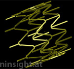
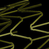
Fig. 1: Numerical models of the two self expandable
stents to be compared (stent 1 left, stent 2 right).
This study compares the performance of two different
stents (see Fig. 1) when deployed in a particular artery. Both stents
are self expandable and consist of a shape memory alloy.
Although there exist a number of parameters describing the performance
of a stent which are independent of the artery, the real performance can
only be assessed by studying the interaction with an artery.
Arterial tissue model. Arterial tissue behaves highly nonlinear
and anisotropic. In addition, nonrecoverable deformations appear during
therapeutic loadings (e.g. due to angioplasty). This behavior can be described
most favourably with the model described in [1], [2] and [4]. It considers
three-dimensional morphological data coming from high-resolution magnetic
resonance (hrMR) imaging and associated histological analyses of an individual
human stenosis. Data from mechanical tests are used to establish constitutive
laws, whereas eight different arterial tissues are considered (see [1]
and [2]). The constitutive laws represent anisotropic and nonlinear material
responses at large strains. Contact. The contact interaction between stent and artery
can lead to serious numerical stability problems or unrealistic solutions
regarding the contact pressure (which is of major interest in stenting
simulations). To avoid this, a special contact algorithm (see [6]) was
used, which satisfies C1 continuity everywhere in the contact
domain, regardless of the structure of the interacting finite-element
meshes. Fluid-Structure Interaction. The stent modifies the arterial
configuration considerably. However, also hemodynamic effects influcence
the situation after stenting. These effects are considered using a Lagrange
multiplier based fictitious domain formulation [7] with a non-Newtonian
blood fluid model. Shape memory alloy. This type of material is used widely,
since it provides great advantages during deployment of the stent. In
this study it is simulated with a specially developed model capable to
replicate the temperatur controlled phase change between austenite and
martensite.
Arterial specimen
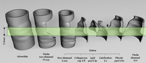
Fig. 2: Arterial specimen exploded into eight
different tissue layers. The region considered for the present simulation
has a length of 5.5 mm and is highlighted in green.
An external iliac artery (male, 68 years) was studied.
The axial in situ prestretch, defined as in situ length / ex situ length
was obtained as λis=1.04. The tissue components were
represented by a NURBS model, which served as a basis for an adaptive
finite element discretization. The individual components are non-diseased
intima I-nos, collagenous cap I-fl (fibrotic part at the luminal border),
fibrotic intima at the medial border I-fm, calcification I-c, lipid pool
I-lp, nondiseased media M-nos, diseased fibrotic media M-f and adventitia
A. The resulting model of the artery is comprised of 8492 hexahedral elements.
Stents
Both stents were geometrically defined by NURBS and discretized with
hexahedral elements. Stent 1 consists of 5236 elements while stent 2
consists of 8496 elements (see Fig. 3). The material used for both stents
is a shape memory alloy which was modeled accurately using a numerical
model capable to simulate the temperature controlled phase change between
austenit and martensite.
Fig. 3: Finite element discretizations for
stent 1 (left) and stent 2 (right).
Results
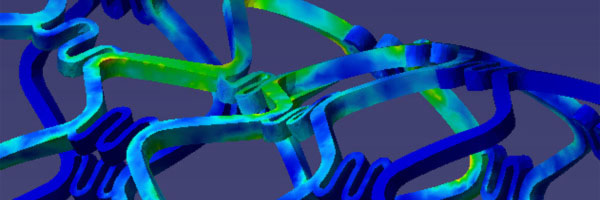
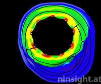
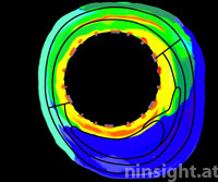
Fig. 4: Von Mises stress
distribution in axis normal sections of the artery due to deployment
of stent 1 (top) and stent 2 (bottom). Black lines indicate borders
between tissue components.
The analysis of stress distributions in sections
of the arterial vessel provides reasonable insight (see Fig. 4). Parameters
to be studied are:
lumen gain due to stenting
stress distribution in individual tissue components and along the
arterial axis
stress distribution at the stent edges (where tissue transitions from
the stented to the non-stented region)
prolapse of tissue between stent struts
turbulence of blood flow due to stent struts
contact pressure between struts and vessel wall
pulsatile diameter amplitude and related fatigue of stent material
several other restenosis related parameters.
These parameters can be used to choose the optimal stent
for a praticular artery, but also to optimize stent geometries.
Conclusion
This study considers a number of important aspects in order
to compare the performance of two different stent products.
These are in particular:
Stress distribution and
lumen gain. In general it can be observed that the investigated
artery becomes less stressed due to stenting with stent 1 than with stent
2 (except in the contact areas between intima and stent struts, where
stent 1 shows higher stresses). However, this is also reflected by a slightly
decreased lumen gain of stent 1, when compared with stent 2. Prolapse. Regarding prolapse, it can be observed that
stent 1 leads to a very different behavior in the diseased and in the
non-diseased region. That is, in the non-diseased region, the stent struts
are deeply sunken into the arterial tissue, which may have advantagous
hemodynamic effects (see below). However, in the diseased region, there
is a much smaller prolapse seen. The reason for this may be associated
with the plaque composition, which gives the arterial wall an increased
stiffness. For stent 2, there is almost no prolapse visible, both in the
diseased and non-diseased region. Hemodynamics. The simulation shows that the effects of
fluid-structure interaction are significant and can not be neglected.
Stent 2 initiates a number of eddies while stent 1 does not. This may
be associated with the strut shape and the prolapse.
References
[1] G. A. Holzapfel, M. Stadler and C. A. J. Schulze-Bauer, A layer
specific three-dimensional model for the simulation of balloon angioplasty
using magnetic resonance imaging and mechanical testing, Annals of Biomedical
Engineering, 30 (2002), 753-767.
[2] G. A. Holzapfel, C. A. J. Schulze-Bauer and M. Stadler, Mechanics
of angioplasty: Wall, balloon, and stent. In: Mechanics in Biology, edited
by J. Casey and G. Bao. New York: The American Society of Mechanical Engineers,
2000, AMD-Vol. 242; BED-Vol. 46, pp. 141-156.
[3] G. A. Holzapfel and M. Stadler, Changes in the mechanical environment
of stenotic arteries during interaction with stents: computational assessment
of parametric stent designs, J. Biomech. Eng., 2004, in press
[4] G. A. Holzapfel, T. C. Gasser and R. W. Ogden, A New Constitutive
Framework for Arterial Wall Mechanics and a Comparative Study of Material
Models, Journal of Elasticity, 61 (2000) 1-48.
[5] Biomechanics of Soft Tissue in Cardiovascular Systems, G.A. Holzapfel
and R.W. Ogden (eds.), Springer-Verlag, Wien New York, 2003.
[6] M. Stadler and G.A. Holzapfel, Subdivision schemes for smooth contact
surfaces of arbitrary mesh topology in 3D, Int. J. Num. Meth. Eng., 2004,
in press.
[7] De Hart, J., Peters, G.W.M., Schreurs, P.J.G., Baaijens, F.P.T., A
three-dimensional computational analysis of fluid-structure interaction
in the aortic heart valve, J. of Biomechanics, 2001.
Here's your opportunity to find out if Ninsight
can help you to solve your biomechanical problems.
If you have a biomechanical engineering problem and want a
quality solution complete our online
information form. We will forward this request the most
appropriate engineer who will contact you to discuss your
problem directly.