Simulation of a natural human aortic heart valve
|
| The human aortic heart valve |
|
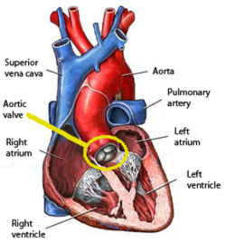 |
Image 1: Schematic sagittal
cross section of the human heart showing the aortic valve. |
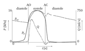 |
Image 2: Distribution of
the aortic pressure (Pao, dashed line) and left ventricular pressure
(Plv, solid line) during the cardiac cycle. The associated flow
is the curve denoted with Q. The symbols AO and AC denote the instants
of valve opening and complete valve closure, respectively. |
The aortic valve is one of the four valves which control
the blood flow through the heart. It is located at the outlet of the left
ventricle at the beginning of the ascending aorta (see yellow circle,
Image 1). The healthy valve opens with minimal resistance and closes to
prevent back flow into the ventricle.
The cardiac cycle can be divided into a systolic and diastolic interval,
see Image 2. During systole an isochoric contraction of the left ventricle
is followed by the ejection of blood into the aorta. During this interval
the aortic valve remains open.
At diastole an isochoric relaxation precedes a filling of the left ventricle
with blood from the atria. During this interval the aortic valve remains
closed. Both mechanical and kinematic aspects are involved in valve functioning
and differ in importance during the course of the cardiac cycle.
In one cardiac cycle three main phases can be distinguished in valve performance:
(i) the opening and (ii) closing phases during systole and (iii) the closed
phase during diastole. For a healthy valve, the opening interval is very
fast (25 to 35 [ms]). The leaflets begin to bulge towards the aorta wall
just before ventricular ejection begins. At the time when the flow in
the ascending aorta has reached 75% of its maximum, the valve is completely
open. In the case of normally working heart valves, the fluid flow remains
laminar, although the Reynolds number reaches up to 4500 at peak flow
[2]. Only when a valve exhibits a malfunctioning, some turbulence might
be expected [1]. |
| Morphology and numerical model |
|
 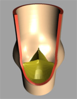 |
| Image 3: Geometrical model of the aortic heart
valve (left full model, right after dissection). |
The natural valve consists of three highly flexible
leaflets and three sinus cavities, see Image 3. Each leaflet can be divided
in two functional areas:
The area near the free edge is known as the coaptive area (also called
the lunulea because of its semilunar shape). When the valve is closed
the outlet orifice of the left ventricle is sealed because the lunuleae
of adjacent leaflets touch each other. In the middle of the free edge
of each lunulea a structural thickening (’nodulus of Arantius’)
is located. Presumably, it acts as a structural reinforcement, allowing
a significant reduction in the height of the lunulea without causing central
regurgitation during a closed valve configuration.
The remaining, non-coaptive area of the leaflet surface is referred to
as the load bearing portion. This part constitutes a fiber-reinforced
composite texture of elastin. The fibers consist mainly of collagen embedded
in a matrix of endothelial cells. In particular, this texture has a three-layered
structure: The ventricularis at the ventricular surface contains
elastin and collagen fibers, the spongiosa (middle layer) contains
acid mucopolysaccharides and some collagen fibers, the fibrosa
(near the aortic surface) contains a dense network of collagen fibers.
A similar layered structure is present in the lunulea, however, the arrangement
of the fibers may be very irregular.
For the numerical model, a short
segment of the aorta with the three sinus cavities as well as the leaflets
were geometrically modeled using NURBS. All tissue components are simulated
mechanically using an anisotropic material model to consider the elastin-collagen
fiber matrix on a multi layered basis. For fluid structure interaction
a Lagrange multiplier based fictitious domain formulation [1] is integrated
within the finite element method. Contact interaction between the leaflets
is based on the publication [3]. The key features of this numerical strategy
are:
- Conventional mathematical discriptions
- Fully coupled approach
- Interaction through kinematical constraints
|
|
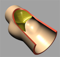 |
| (a) t=0.0 [s] |
|
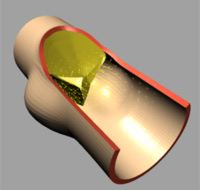 |
| (b) t=0.02 [s] |
|
 |
| (c) t=0.04 [s] |
|
 |
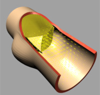
| (d) t=0.1 [s] |
|
 |
| (e) t=0.3 [s] |
|
 |
| (f) t=0.5 [s] |
|
|
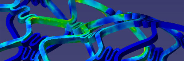
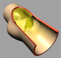
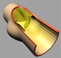
| Image 4: Fluid dynamics during systole. |
The deformation of both the leaflets and the ascending aortic wall as
well as the velocity vector field is given in Image 4 (a) to (f). In frame
(a) the valve is shown in its initial (stress free) configuration, corresponding
to the closed position. During the acceleration phase (frame (b)) a forward
flow is observed throughout the whole fluid domain, including the sinus
cavity (i.e. wash-out). For the fully opened valve (frame (d)) the flow
is concentrated in the center. Almost no flow can be seen in the sinus
cavity. At the moment of complete valve opening, however, the flow has
started to decelerate already. During the deceleration phase recirculation
at the leaflet free edge precedes vortex development in the sinus cavity
and the valve is closed again (frames (e) and (f)).
|
|
The numerical simulation of
a human aortic heart valve provided detailed insight into the normal flow
pattern. This information is indispensible when it comes to designing
artificial heart valves, which aim to generate a flow pattern similar
to the natural valve. The presented strategy also allows to study innovative
designs of artifical valves under arbitrary conditions. |
|
[1] De Hart, J., Peters, G.W.M., Schreurs, P.J.G.,
Baaijens, F.P.T., A three-dimensional computational analysis of fluid-structure
interaction in the aortic heart valve, J. of Biomechanics, 2001.
[2] Nerem, R.M., Seed, W.A., 1972. An in vivo study of aortic flow disturbances.
Cardiovascular Research, 6(1): 1-14.
[3] M. Stadler, G. A. Holzapfel and J. Korelc, Cn-continuous
modeling of smooth contact surfaces using NURBS and application to 2D problems,
Int. J. Numer. Meth. Engng., 57:15 (2003), 2177-2203.
|