| Optimization of a mechanical heart
valve |
|
The heart has four chambers. The upper
two are the right and left atria. The lower two are the right
and left ventricles. Blood is pumped through the chambers,
aided by four heart valves. The valves open and close to let
the blood flow in only one direction.
What are the four heart valves?
- The tricuspid valve is between the right atrium and right
ventricle.
- The pulmonary or pulmonic valve is between the right ventricle
and the pulmonary artery.
- The mitral valve is between the left atrium and left ventricle.
- The aortic valve is between the left ventricle and the
aorta.
Each valve has a set of flaps (also called leaflets or cusps).
When working properly, the heart valves open and close fully.
Heart valves don't always work as they should. A person can
be born with an abnormal heart valve, a type of congenital
heart defect. Also, a valve can become damaged by
- infections (e.g. infective endocarditis)
- changes in valve structure in the elderly
- rheumatic fever
|
|
 |
A mechanical (or artificial) heart valve
is a man-made device that is used to replace one of a patient’s
own damaged or diseased heart valve that cannot be repaired.
A biological valve, from either an animal (xenograft) or a
deceased human donor (allograft) may also be used to replace
the patient’s original valve.
In most cases, the use of a mechanical heart valve can lengthen
or even save a patient’s life. The valves are durable
and can last 30 years or longer. However, there is a risk
of complications, and most patients will need to take anticoagulants
for the rest of their lives to reduce the risk of blood clot
formation.
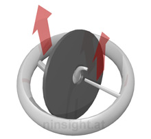
Here we perform a numerical study of a valve construction
based on a curved central guide strut and a flat disc. This
has two advantages: (i) It allows assembly of the valve and
disc without imparting stress on the valve housing and (ii)
it allows the disc to move out of the annular plane (which
is the tightest constricture of the resultant outflow tract).
This type of valve is produced by Medtronic. |
|
| Turbulence in the cardiovascular system
leads to higher flow resistance, resulting in increased pressure
gradients. Furthermore, elevated levels of turbulent shear
stresses may create hemolysis or platelet activation [1],
[5]. This may in turn lead to thrombosis [8] and embolism.
It was also shown that turbulent shear stresses can be associated
with the development of aortic aneurysms [3], [6].
The damage done to red blood cells can be described as a function
of spatial distribution, exposure time and magnitude of turbulent
shear stresses. In particular, in [7] and [9] the critical
parameters of turbulent shear stress were identified, which
lead to lethal or sublethal damage of blood cells.
The goal of an optimal heart valve is to retain a near physiologic
turbulence profile. The benefits are minimal pressure gradients
and very low levels of thrombosis and thromboembolism. This
was experimentally prooved for the Medtronic Hall valve in
[2].
To achieve this design goal, computational fluid dynamics
simulations are of great advantage. The valve and the adjacent
arteries were modeled using NURBS to facilitate (i) adaptive
mesh refinement and (ii) a parametric geometrical model which
is suitable for design optimization. The fluid zone was meshed
automatically by a hexahedral mesh using approx. 400.000 elements.
The fluid problem was modeled using a non-Newtonian model
which was solved using a modified SIMPLE algorithm. The moving
bodies were considered using fluid structure interaction considered.
Thereby, the arterial wall is simulated as a hyperelastic
medium and the valve disc as a rigid, but movable body. The
results of the simulation are shown in Fig. 1 and 2.
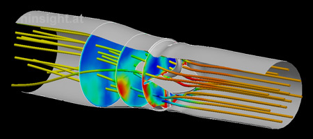 |
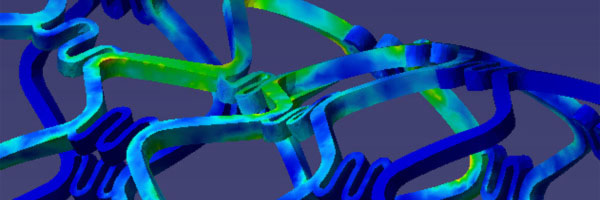
Fig. 1: CFD
simulation of the mechanical heart valve. The image
depicts the flow situation at the systolic phase (the
valve is fully opened under 75°). Streamlines are
colored by the local pressure. Section planes show the
turbulent dissipation. |
|
|
Despite a common belief in a symmetrical
(i.e., bullet-shaped) flow pattern in the ascending aorta,
research has confirmed that natural aortic flows are eccentric—with
the region of highest velocity occurring in the non-coronary
sinus [Paulsen et al.].
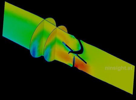 |
| Fig. 2: Velocity magnitude at fully
opened valve (three representative sections). |
|
|
- Kroll
MH, Hellums JD, McIntyre LV, et al. Platelets and Shear
Stress. Blood 1996;88:1525-41.
- Kleine
P, Perthal M, Nygaard H, et al. Medtronic Hall versus St.
Jude Mechanical Aortic Valve: Downstream Turbulences with
Respect to Rotation in Pigs. J Heart Valve Dis 1998;7:548-55.
- Nichols
WW, O'Rourke MF. McDonald's Blood Flow in Arteries. Theoretic,
Experimental, and Clinical Properties. 3rd ed. Philadelphia:
Lea & Febiger, 1990;54-71.
- Paulsen
PK, Nygaard H, Hasenkam JM, et al. Analysis of Velocity
in the Ascending Aorta in Humans. A Comparative Study Among
Normal Aortic Valves, St. Jude Medical and Starr-Edwards
Silastic Ball Valves Int. J Artif Org 1988; 11:293-302.
- Ruggeri
ZM. Mechanisms of Shear-Induced Platelet Adhesion and Aggregation.
Thromb Haemost 1993:70:119-123.
- Stein
PD, Sabbah HN. Hemorheology of Turbulence. Bioheol 1980;17:301-19.
- Tillmann
W, Reul H, Herold M, et al. In Vitro Wall Shear Measurements
in Aortic Valve Prostheses. J Biomech 1984;17:263-79.
- Yoganathan
AP, Wick TM, Reul H., The Influence of Flow Characteristics
of Prosthetic Heart Valves on Thrombus Formation. I: Butchart
EG, Bodner E (eds.) Current Issues in Heart Valve Disease:
Thrombosis, Embolism and Bleeding. London: ICR, 1992;123-48.
- Yoganathan
AP, Woo Y-R, Sung H-W. Turbulent Shear Stress Measurements
in Aortic Valve Prostheses. J Biomech 1986;19:433-42.
|